Inspecting Electrical Connections
Inspections of electrical systems and components cover a vast and varied spectrum. Learning to recognize proper and improper installations and defective systems is a continuing process for home inspectors.
In a typical workweek, a home inspector will likely come across issues involving improper wire size, grounding or bonding issues, incorrect overcurrent protection, degradation of equipment, open splices and uncovered junction boxes…just to name a few.

In this article, I’ll focus on electrical connections. All electrical circuits terminate in some form at their point of origin and also at their end destination. Depending on the circuit design, splice junctions and device connections add more termination points.
The wiring that supplies a branch circuit in the average home originates in the distribution panel at the overcurrent device terminals for the ungrounded conductor, and at the neutral bar and grounding bar for the grounded and grounding conductors. The “home run” (that is, wiring from the overcurrent device to the first component in the circuit) connects to the terminals on the outlet, commonly a switch or receptacle. From that point, the circuit will generally continue with another run of wire to the next outlet (for example, a receptacle, switch or fixture). The circuit may involve 10 to 15 (or more) devices, which could require up to 100 points of connection.
Loose or damaged connections are commonplace in electrical systems. The points of connection are the weak links in any wiring system. The more connections, splices or terminations, the more potential for problems. Knowing how to identify these problems by visual inspection is probably the most critical part of the home inspector’s electrical evaluation.
Circuit-Breaker Terminals
Terminals on circuit breakers have a variety of designs, depending on the manufacturer and the time of manufacture. Terminals are identified and labeled to specify temperature rating, wire material rating, wire size range and torque specification. If the terminals are rated for two conductors, this also will be specified.
Currently, only two manufacturers—Eaton and Square D—provide residential-grade circuit breakers that allow two conductors (Photo 1). Eaton, formally Cutler Hammer, sells two residential lines of load-center panels: CH and BR. Only CH breakers are rated for two wires. They are easy to recognize by their tan-colored toggle for the breaker switch. Square D terminals have a top and bottom pressure plate that has slots on each side for the wires. They are available on both their QO and HOM lines of breakers.
The Eaton design is a tapered slot with a set screw. These terminals are only available on 15-, 20- and 30-amp breakers. I often hear or read comments from inspectors that the two wires must be the same size and must both be either solid or stranded; however, there is no requirement for this in the listing by the manufacturer. The Square D terminal, for example, can have a #14 wire on one side and a #10 on the other side, and one could be stranded and the other solid. They cannot both be in the same slot, however.
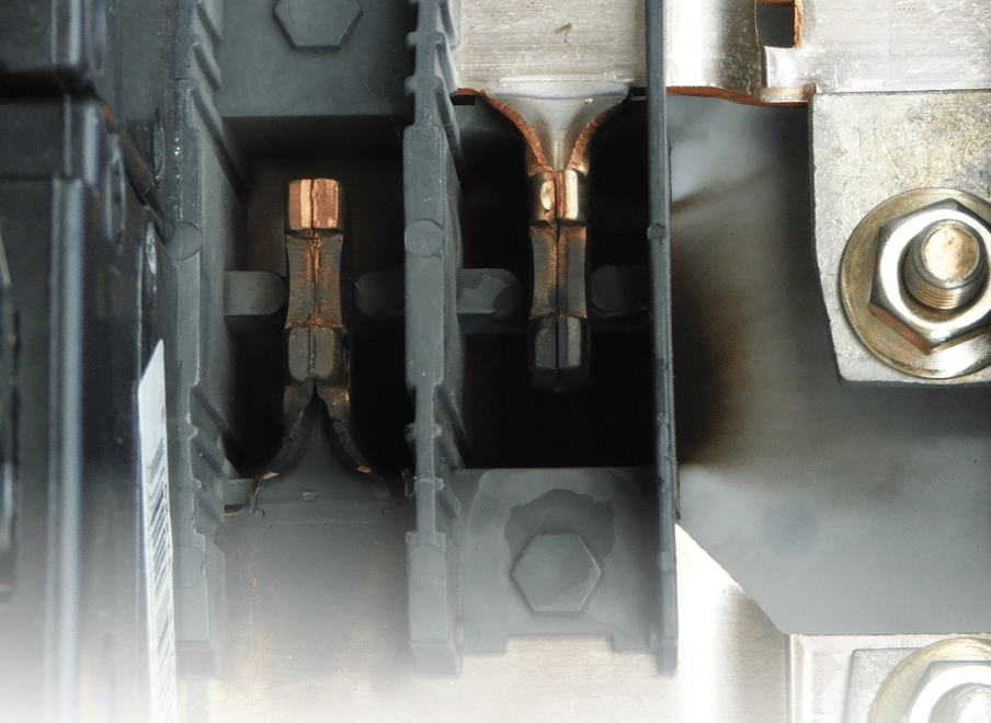
Eaton terminals also will allow two wires of different gauge. Both styles only allow two copper wires. If aluminum is used, only one can be connected. Some older designs by other manufacturers allowed two wires, but those designs are no longer made (Photos 2 and 3).
A common misconception by home inspectors is that when a second wire is added to a breaker terminal (even one designed for two wires), another circuit has been added and this could cause an overload. First, even if the breaker had 10 wires attached, it is still one circuit. Here’s a simple rule: One overcurrent device = one circuit. Second, as far as causing an overload, a second wire is simply a connection to provide a parallel branch of the circuit; it is no different from a splice downstream at a junction box or a connection at an outlet, and it causes no more or no less potential for an overload. Inspectors have no way of knowing what the amperage load is or could be on each of the wires without doing additional testing and measuring, which is beyond the scope of a standard home inspection.

Photo 1. Left to right: Square D breaker designed for two wires, Eaton/Cutler Hammer CH breaker designed for two wires and Siemens breaker designed for one wire.

Photo 2. Older GE breaker designed for two wires.

Photo 3. Older Bryant tandem breaker designed for two wires for each circuit.
Double-taps and multi-taps are common defects found in electrical inspections. Terminals that are not designed for two wires may not provide a good connection, which will cause higher resistance at the connection and, thus, temperature rise. Neutral terminations allow only one conductor per terminal.
It is common to see double-tapped neutrals in older panels. Some inspectors and electricians think that this was once an acceptable installation. Many code inspectors did not enforce one wire per terminal because none of the code references specifically mentioned neutrals.
NEC Article 110.3(B) refers to manufacturer’s specifications, which designate only one neutral conductor per terminal. NEC Article 110.14(A) states: “Terminals for more than one conductor and terminals used to connect aluminum shall be so identified.” UL bulletin 67 also specifies one neutral per terminal. These requirements go back to at least the 1960s. Finally, in the 2002 edition of the NEC, the confusion was put to rest by Article 408.21, which includes a specific requirement of one neutral per terminal.
Codes aside, logical thinking should prevail. The neutral in a 120-volt circuit carries the same amount of current as the hot conductor. They deserve equal respect in termination requirements. A terminal that is not designed for more than one wire is a potential safety and performance concern, and should be corrected (Photo 4).

Photo 4. Double- and multi-tapped neutrals.
Correcting double-taps is fairly simple. One wire can be connected to the breaker terminal and then spliced to the two-load wires with a proper connector such as a wire nut. This is perfectly acceptable. It should be noted, however, that this type of splice correction for double-tapped neutrals needs a closer look. It should be confirmed that the two spliced neutrals are on circuits of opposite phase legs. The breakers (normally a double-pole breaker) for the two circuits must be connected with a handle tie to ensure this. If the two load neutrals are on circuits of the same phase leg, the pigtail wire to the terminal will carry the sum load of both circuits and it could be undersized. It is unlikely that the amperage of both circuits would be heavily loaded enough at the same time to cause a problem, but it is possible.
As mentioned earlier, there are many different designs used in breaker terminals. Some are significantly better than others. The types with a top pressure plate are good because the contact area to the wire is large. An older design had a bottom plate with upturned edges and a screw head to secure the top of the wire. Most installations with this type are a straight-in connection (Photo 5). This can sometimes cause problems because of the small contact with the screw head. A better application with this type terminal is to wrap the wire in a clockwise direction two-thirds of the way around the screw. Unfortunately, this is rarely done.

Photo 5. Loose “straight-in” connection on wire-binding screw. This design was only allowed for #10 gauge and smaller per 110.14(A).
Lugs, Wire Nuts and Other Connectors
Wire terminals and lugs are designed for specific wire sizes. Common improper installations include cutting strands to make an oversized wire fit the terminal (Photo 6) or separating the strands of a large conductor into “pigtails” to fit two smaller terminals. (This is often seen with large-gauge stranded equipment grounds and neutrals.)
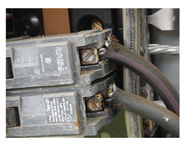
Photo 6. Wires too large for breaker terminals.
Wire nuts, split bolts, set-screw connectors and others all have specific use applications as well. Wire nuts do have a limit of how many wires are allowed, but this limit is often ignored by the installer. (Side note: I refer to mistake-makers as installers because a person bearing the title of electrician should certainly know better.)
Barrel lugs, such as those used for service-conductor connections, often are stamped with detailed information on the face or side of the lug (for example, wire size, number of conductors, wire material and temperature rating).
Solid and stranded wire have different characteristics, and work differently with the various types of terminals and connectors. Most breaker terminals, wire nuts, split bolts and barrel lugs are compatible with both. Crimp connectors, such as butt splices, spades and rings, can be used with solid or stranded conductors. Many electricians (including myself) will use these only with stranded wire because solid wire tends to work loose with crimp connectors.
Push-in connectors should only be used with solid wire. Wire-binding screw terminals, such as those on receptacles and switches, work fine with solid wire, but stranded wire is more difficult to properly wrap well around the screw.
Using spades and ring-crimp connectors on stranded wire for connecting to wire-binding screws makes a good, solid connection, but “technically” it would be wrong because spade terminals have not been evaluated and are not “listed” for that application by UL. It’s puzzling to me that UL seems to favor the push-in connections on listed receptacles and switches over the much better connection of a spade or ring terminal.
Many installers use the push-in connectors that are available on the cheaper, lower-grade receptacles and switches. These are only allowed on 15-amp branch circuits and only with #14 solid copper. They provide a faster installation method and therefore are popular.
I’ve seen many failures on these connections over the years. The design is simply bad because it depends on spring tension for the connection. Springs weaken over time and the contact area is minimal. Back-wired/push-in connections are compliant by manufacturer’s specs and are not considered a defect; however, in my opinion, they are not a best-practice installation.
Electricians wrap the binding screw or use a better grade outlet with pressure-plate terminals. Connections on switches and receptacles are normally not visible to the home inspector unless covers are removed or are missing. I mention this to stress the importance of good and proper connections.
So, what could be the consequences of a loose electrical connection? There could be loss of power, damaged devices and equipment and, most importantly, a loose electrical connection could cause a fire. When a connection point is loose, resistance at that point increases which, in turn, produces heat. A “glowing connection” is a term used in the industry to describe an intense heating condition at loose electrical connections. According to some studies, the terminal temperature can reach 1,000 degrees F on a standard household receptacle under load when the connection is loose.
I recommend reading these good articles on this subject:
- “A Glowing Connections Experiment” (www.experts.com/Articles/glowing-connection-expiriment-by-Donan-Engineering)
- “The Basics of Electrical Overheating” (www.ecmweb.com/ops-amp-maintenance/basics-electrical-overheating)
Newer technology, such as arc fault devices, can help prevent damage from loose connections only if there is arcing sufficient enough to affect the wave pattern of the circuit and be recognized by the device. Many times, there is little or no arcing and therefore no specific protection. The load current in the circuit is within the parameters of the overcurrent protection, so the breaker or fuse will not open and disconnect the power (Photos 7 and 8). Important note: Both of the circuits shown in Photos 7 and 8 were still energized when I found them. The circuit breakers did not trip.
My guess is that the next major technological advancement will be a thermal-protection sensor that will be installed in outlet devices. That technology is already available via thermal switches and overloads, but apparently there is not yet a cost-effective value for this application.

Photo 7. Resulting damage on switch from a loose connection.

Photo 8. Loose connection at pull-out bar in cheap furnace disconnect.
Safeguards Against Loose Connections
The first line of defense to prevent loose connections is in the initial installation. If the installer is careless, untrained or both, the chances of problems are greatly increased. It is my hope that electricians will have proper training and pride of craftsmanship that will result in proper installations.
The basic requirements for proper installations
are as follows:
- Proper torque: Torque specifications should be followed. Too tight and too loose both cause problems. Note: The 2017 NEC requires using calibrated torque wrenches and screwdrivers for terminal connections. 110.14(D).
- Clean, dry terminals and wires: Connection points should have no corrosion, oxidation or moisture. Antioxidant compounds can be beneficial. These are sometimes recommended by manufacturers. They are not required by the NEC.
- Proper wire size-to-terminal match: Follow specifications for wire size.
- Proper material compatibility: Follow specifications to avoid dissimilar metal issues for aluminum and copper conductors.
- Number of allowed conductors per terminal: Follow the listing specifications.
In existing installations, the best way to prevent issues is to have the system inspected. This is where home inspectors can play an important role. Inspectors should learn to identify potential issues when checking panels. Visual inspections are limited, but they can reveal issues if the inspector follows good practices.
Inspecting a panel properly takes some time. Look at each terminal individually for the following items (some are shown in Photo 9):
- discoloration
- properly stripped wires
- double-taps
- proper wire size for lugs and breakers
- signs of corrosion and oxidation
- melted insulation

Photo 9. Discoloration on lug and melted insulation on wire.
Another common loose connection point in older homes is in a receptacle socket. Old receptacles lose tension in the contact blades over time. This can cause arcing and intense heat elevation. Important note: If your receptacle tester falls out when you let go of it, this is a defect and should be reported.
Circuit breaker stab-to-bus connections also can be a point of loose connection. Many designs are used. Some older designs and commercial designs use bolt or screw connections to the bus, which provide a best-case connection if properly torqued. All currently made residential lines use spring tension clips that snap to the bus stabs. Again, string tension weakens over time and can become loose. Sometimes, these failures are visible to inspectors (Photos 10 and 11), but often they are not. Some older brands (in my opinion, Zinsco/Sylvania was probably the worst) would actually fall off of the bus. Only breakers that are listed for use in a particular panel should be used.

Photo 10. Damaged bus stab.

Photo 11. Arc burns on bus.
Thermal imaging cameras are commonplace in the home inspection industry today. These can be useful tools to find loose and hot-spot connections. Conversely, they are useless if the scan is done on circuits that are under no load at the time of the scan. The circuit must be under a sufficient load for a thermal anomaly to appear.
Proper training is also imperative for accurate interpretation of the scan. A normally loaded circuit will appear “dangerously hot” to an untrained thermographer when the elevated heat of the wiring is actually normal (Photo 12). The wires in a normally loaded circuit will be uniform in the temperature signature from the point of connection to where it leaves the panel. A hot spot or loose connection under load will be more elevated in temperature, and the wire temperature will decrease as it gets farther away from the connection point (Photo 13).

Photo 12. Thermal image of circuit under normal load.

Photo 13. Thermal image of loose connection at a breaker terminal (photo credit: Charles Buell).
I mentioned earlier that terminations in receptacle and switch boxes are not normally visually accessible and are beyond the scope of a typical home inspection. We can only report on and inspect what we can see. Signs of amateur work, homeowner installations and what I like to call “brother-in-law” wiring are what we might see in panels, attics and crawl spaces. When these signs are present, it is good practice to recommend a full evaluation of the electrical system by a qualified inspector or electrician (not an installer). That recommendation might just prevent a catastrophe.
To Read the Full Article
ASHI offers its members unparalleled resources to advance their careers. ASHI offers training for inspectors at all levels of knowledge and experience, including resources about all major home systems. Members benefit from a vast network of experienced professionals, providing a community for mentorship and knowledge sharing..
In this Issue

FIND A HOME
INSPECTOR
Professional Networking
Grow your professional network, find a mentor, network with the best, and best part of the community that’s making home inspection better every day.
