The Word: Common Vent
Once again, The Word invites you to travel into the dark realm of subjects that are sometimes misunderstood by home inspectors. The Word hopes you will find this trip informative and maybe a little entertaining.
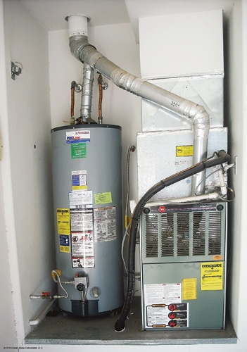
The Word’s subject this month is common vent, as in when you connect two or more fuel-burning appliances to one vent (see Photo 1). The Word finds this subject interesting because inspecting a common vent system involves more than just ensuring that the larger Btu appliance connects below the smaller Btu appliance, and because knowing more about these systems will help you anticipate and diagnose venting problems.
Photo 1
We’ll mostly discuss manufactured common venting systems for gas appliances in this article. For more on using a chimney as a vent for gas appliances, see the January 2012 Reporter.
Remember when reading all The Word columns that we’re discussing general principles. Something you see in the field isn’t always wrong just because it doesn’t comply with a general principle. Local building codes, manufacturer’s instructions and engineered designs trump general principles.
What is the vent?
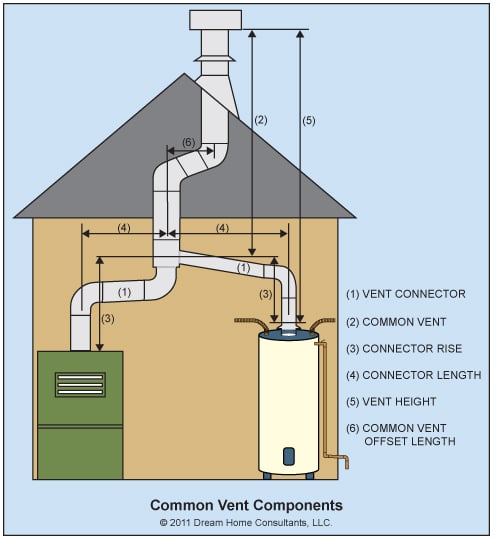
This may seem like a question for Captain Obvious, but the answer is not as simple as it seems. What most of us think of as the vent is really the vent system. The vent system begins at the draft hood or flue collar and ends at the listed vent cap. The vent system consists of two parts: the vent and the vent connector.
In a common vent system, the vent begins at the fitting where the appliances connect. Everything before that fitting is a vent connector. Figure 1 demonstrates this. This distinction is particularly important for common vent systems because the size of the common vent and of each connector is determined individually.
Basic common vent rules
Some basic common vent rules apply to all common vent systems regardless of the fuel type.
- Connect the larger Btu/hour appliance vent connector below the smaller Btu/hour appliance vent connector. Connect the smaller vent connector as high as possible in the room and still maintain clearance to combustible materials.
- Do not install vent connectors for gas appliances directly across from each other unless the angle at the connection is less than 45° relative to vertical.
- Do not common-vent solid-fuel burning appliances with each other and with other appliance types. For example, do not common vent two wood-burning fireplaces and do not common-vent a wood-burning fireplace and a gas-burning fireplace.
- Do not common-vent natural draft with appliances that use a positive-pressure draft. Remember that the draft inducer fans in medium-efficiency furnaces don’t put the vent under positive pressure.
- Be wary of common-venting appliances located on different floors. These vent systems are more complicated. See International Residential Code Appendix B for more about common-venting gas appliances on different floors.
Connectors to common vents
A connector to a gas appliance common-vent may be a Type B vent connector or a single-wall vent connector. A Type B vent is always acceptable as a vent connector for gas appliances. Single-wall vent connectors are not allowed in attics and crawl spaces and may not be allowed in any unconditioned space in very cold areas of the country (we’re talking places like northern Minnesota here) because single-wall vent connectors may not get hot enough to allow effective combustion product flow and because they are prone to condensation that will damage the connector. Single-wall vent connectors may not penetrate interior walls, floors and ceilings. They may penetrate exterior walls and they may run directly through the roof.
Most single-wall vents and vent connectors that The Word sees are made from galvanized steel. When galvanized steel is used, a single wall-vent connector should be approximately 28 gage (0.018 inch) or thicker. The Word has noticed that some people are installing connectors and fittings labeled as being 30 gage, which is not allowed and may deteriorate and leak combustion products over time. For comparison, a single-wall vent (not a vent connector) should be approximately 23 gage (0.0304 inch).
The length of any vent connector to a gas appliance vent should be as short as is practical to help avoid backdrafting. The maximum length of a vent connector to a common vent is 1 ½ times the diameter of the connector expressed in feet. For example, the maximum length of a 3-inch diameter common vent connector is 4 ½ feet and the maximum length of a 4-inch diameter common-vent connector is 6 feet. Longer length vent connectors are allowed, with reductions for connector Btu/h capacity.
All vent connectors should contain no more than two 90° elbows or any combination of fittings that add up to 180° (without Btu/h capacity reduction). This, too, helps avoid backdrafting. Additional elbows are allowed, with reductions for connector Btu/h capacity.
The IRC contains provisions that allow Btu/h capacity reductions for long-length connectors and connectors with more than 180° of elbows. It’s not our job, however, to calculate these reductions. The most practical thing for most of us to do if we see common-vent connectors beyond these parameters is to call for further evaluation.
It’s possible to connect two or more gas appliances to one vent connector to create a vent-connector manifold that connects to a common vent. The vent-connector manifold becomes like a common vent. The vent-connector manifold size and the size of the common vent are determined according to the appliance manufacturer’s instructions. The Word has seen only a couple of these. You may want to call for further evaluation if you encounter this rare animal.
Common vents
A common vent for gas appliances should be a Type B vent, a Type L vent or a masonry chimney. The restrictions on installation and use of single-wall vents make them impractical for use as a common vent.
The ideal common vent is vertical, but this isn’t always possible. Non-vertical sections, called offsets, are sometimes necessary to get around obstructions or are installed for aesthetic reasons to get the vent-roof termination on the back side of the home. A common-vent offset should not be longer than 1 ½ times the vent diameter expressed in feet. A 6-inch diameter common-vent offset should not be longer than 9 feet. There are no prescriptive rules in the IRC that allow for longer common-vent offsets, so any longer offset should be engineered.
A common-vent offset can’t happen without at least two elbows and, as we know, elbows and non-vertical vent sections are less efficient at expelling combustion gasses. The common-vent capacity must be reduced for each elbow. Again, it’s not our job to calculate vent-capacity reductions. If the common-vent offset length is within allowed length limits and there’s no evidence of venting problems, then there’s a good chance that the vent system is functioning properly and there’s probably no need to worry about the elbows.
Common-vent and vent-connector size examples
Although it isn’t our job to calculate vent and vent-connector size, it seems remiss to go through all of this explanation without offering some examples about how to recognize possible vent and vent connector sizing problems. Keep in mind that the following is a very simplified summary of complex gas appliance common-vent system sizing rules and tables. These examples might be similar to situations you see in the field. There are many possible situations. Spending a little time with the IRC vent tables in Section G2428 will give you a better feel for when you might want to question situations that are common in your area.
A 3-inch-diameter vent connector is the most common connector serving a 50-gallon draft hood-equipped water heater (40k Btu). A 3-inch connector may be too small for common-vent system heights less than 30 feet and is likely too small for common vent system heights less than 15 feet.
A 4-inch-diameter vent connector is the most common connector serving a largerinduced-draft, medium-efficiency furnace (100k+ Btu). A 4-inch connector may be too small for common vent system heights less than 15 feet and is likely too small for larger furnaces at common vent system heights less than 10 feet.
A 5-inch-diameter common vent is the smallest practical size to serve a 50-gallon draft hood-equipped water heater (40k Btu) and a larger medium efficiency furnace (100k+ Btu) at common vent system heights greater than 15 feet with no offsets. A 6-inch-diameter common vent should have enough capacity to serve most combinations of draft hood-equipped water heaters and medium-efficiency furnaces at any allowed common-vent system height, including an allowance for one offset.
The bottom line
A common vent is a cost-effective means to vent two or more appliances. It’s important that all vent components be properly sized and configured to avoid backdrafting of combustion products and to avoid damaging the vent system. Vent systems that are too small may “clog up” with excess combustion products and result in backdrafting of combustion products, including carbon monoxide, into the home. Vent systems that are too large may not develop enough draft to allow the combustion products to reach the top of the vent. This also can result in backdrafting and in condensation that can rust out the vent from the inside.
Memo to Vulcan and the other fire gods: The Word does not reside on Mt. Olympus (just at its base) and welcomes other viewpoints. Send your lightning bolts or emails to Bruce@DreamHomeConsultants.com. The thoughts contained herein are those of The Word. They are not ASHI standards or policies.
Bruce Barker, Dream Home Consultants, Peoria, Ariz., has been building and inspecting homes since 1987. He is the author of “Everybody’s Building Code” and currently serves as chair of the ASHI Standards Committee. To read more of Barker’s articles or if you need a presenter at your next chapter event, go to www.dreamhomeconsultants.com.
To Read the Full Article
ASHI offers its members unparalleled resources to advance their careers. ASHI offers training for inspectors at all levels of knowledge and experience, including resources about all major home systems. Members benefit from a vast network of experienced professionals, providing a community for mentorship and knowledge sharing..
In this Issue

FIND A HOME
INSPECTOR
Professional Networking
Grow your professional network, find a mentor, network with the best, and best part of the community that’s making home inspection better every day.


